Pcom week2
09/18/21
Digital Input and Output with an Arduino
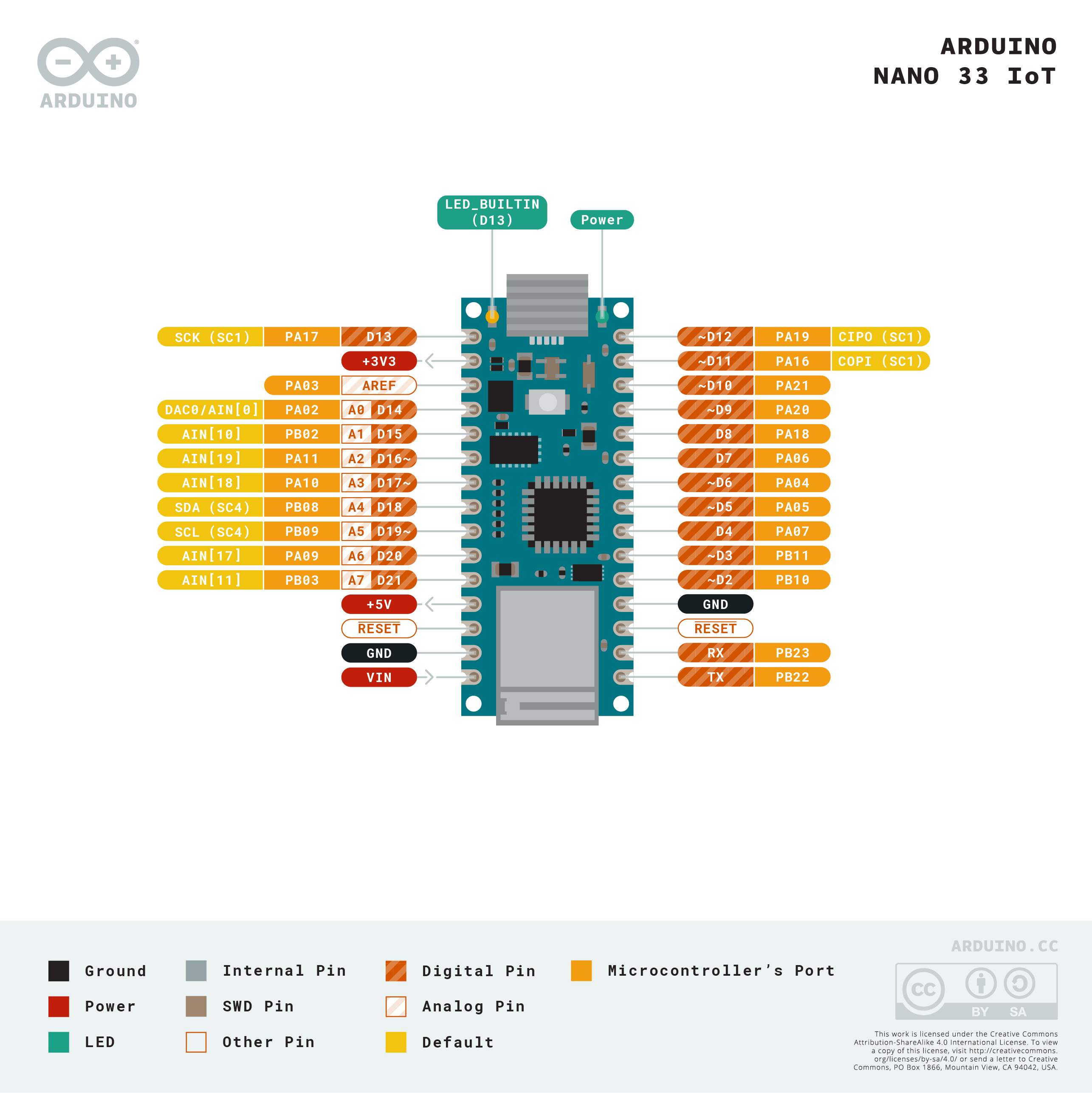 Arduino Nano’s input/output, digital/analog pins
Digital input (pushbutton)
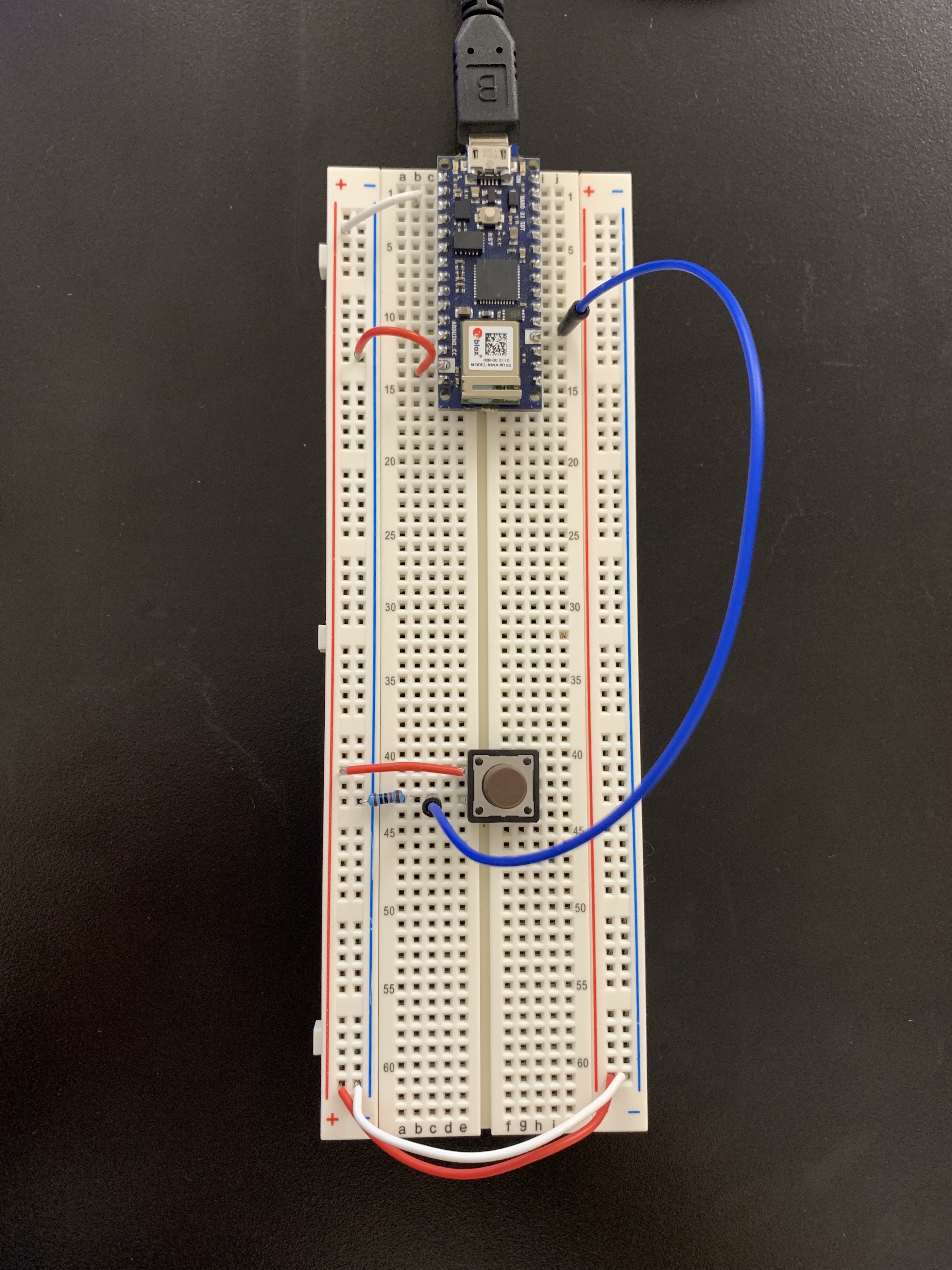 First, I prepared the breadboard. The 3.3 volts and ground pins of the Arduino are connected by red and white wires, respectively. And then I put pushbutton and connect it with 10k ohm resistor, using blue wire to connect them to digital pin 2.
Add a digital output (LEDs / Buzzer)
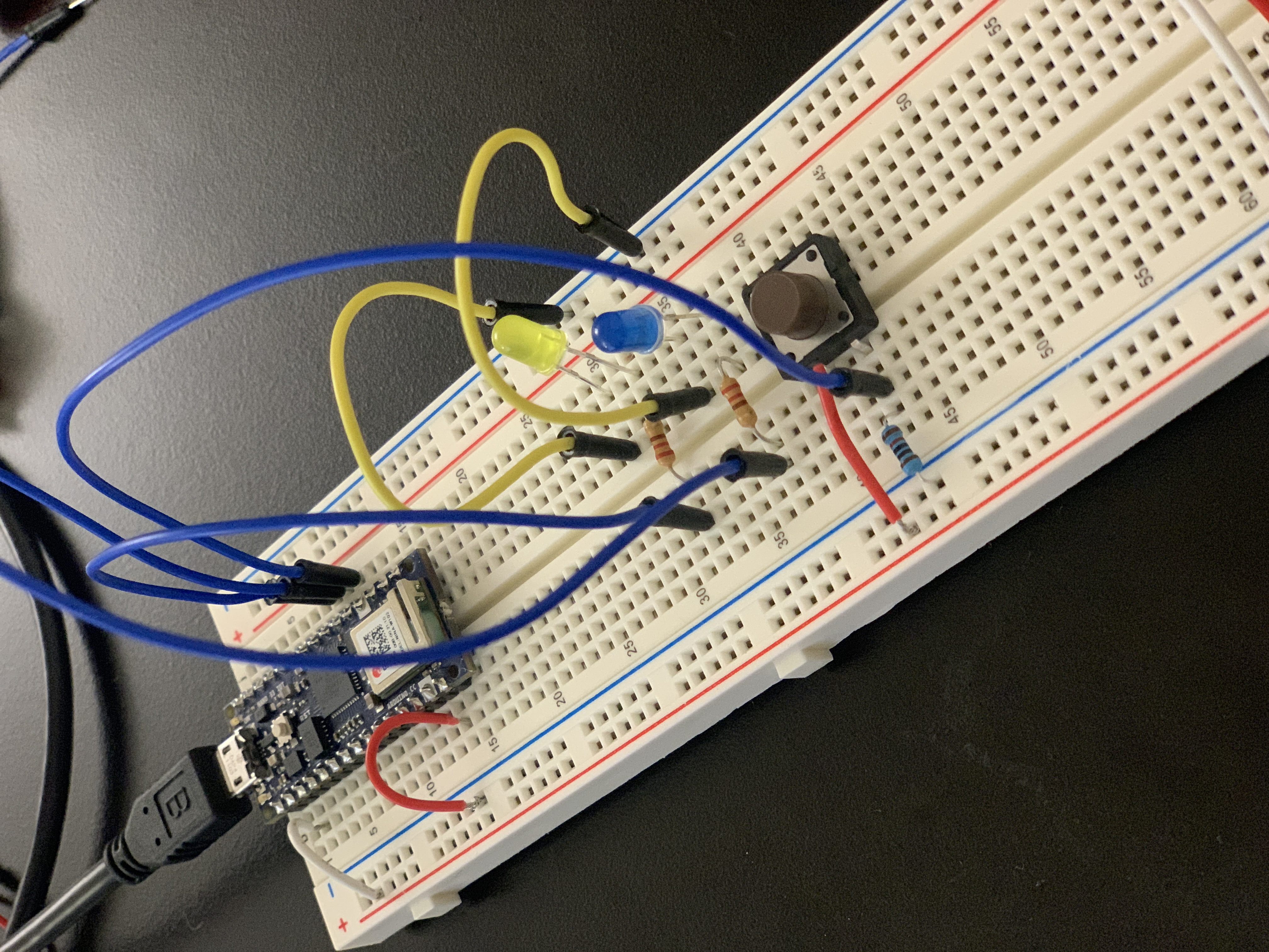
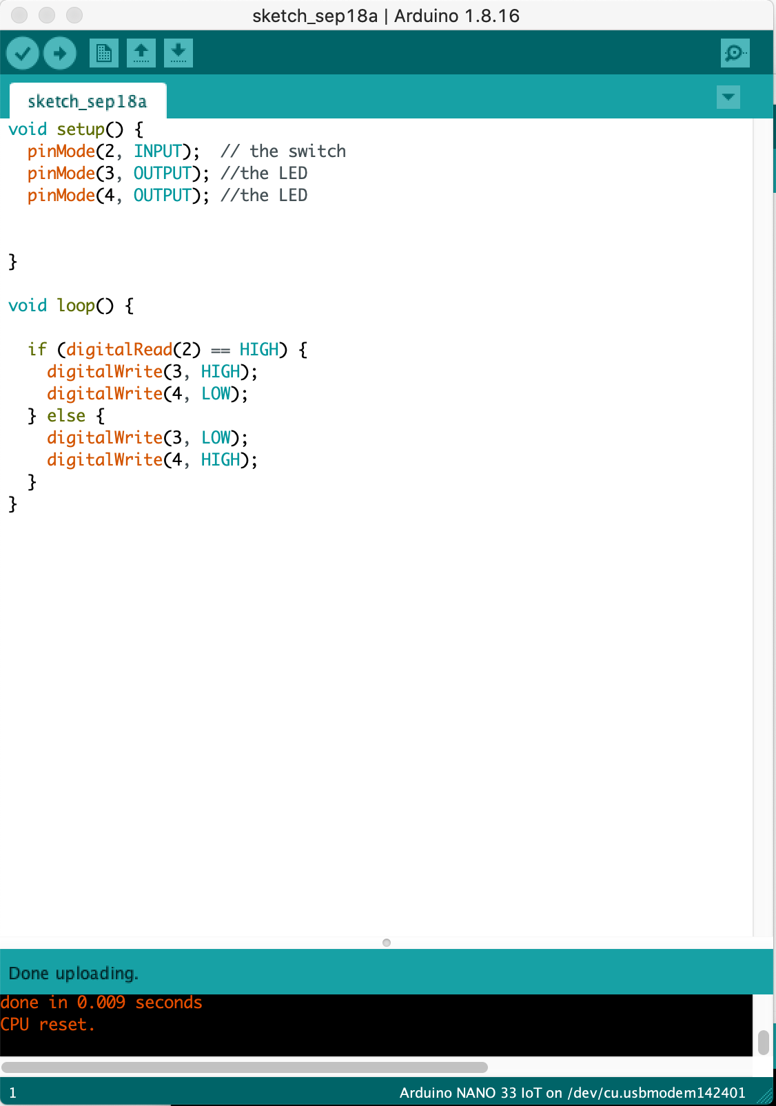
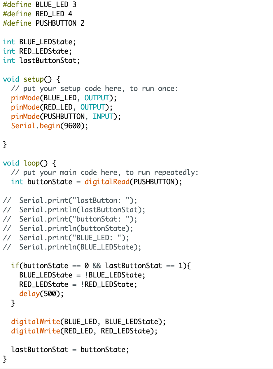
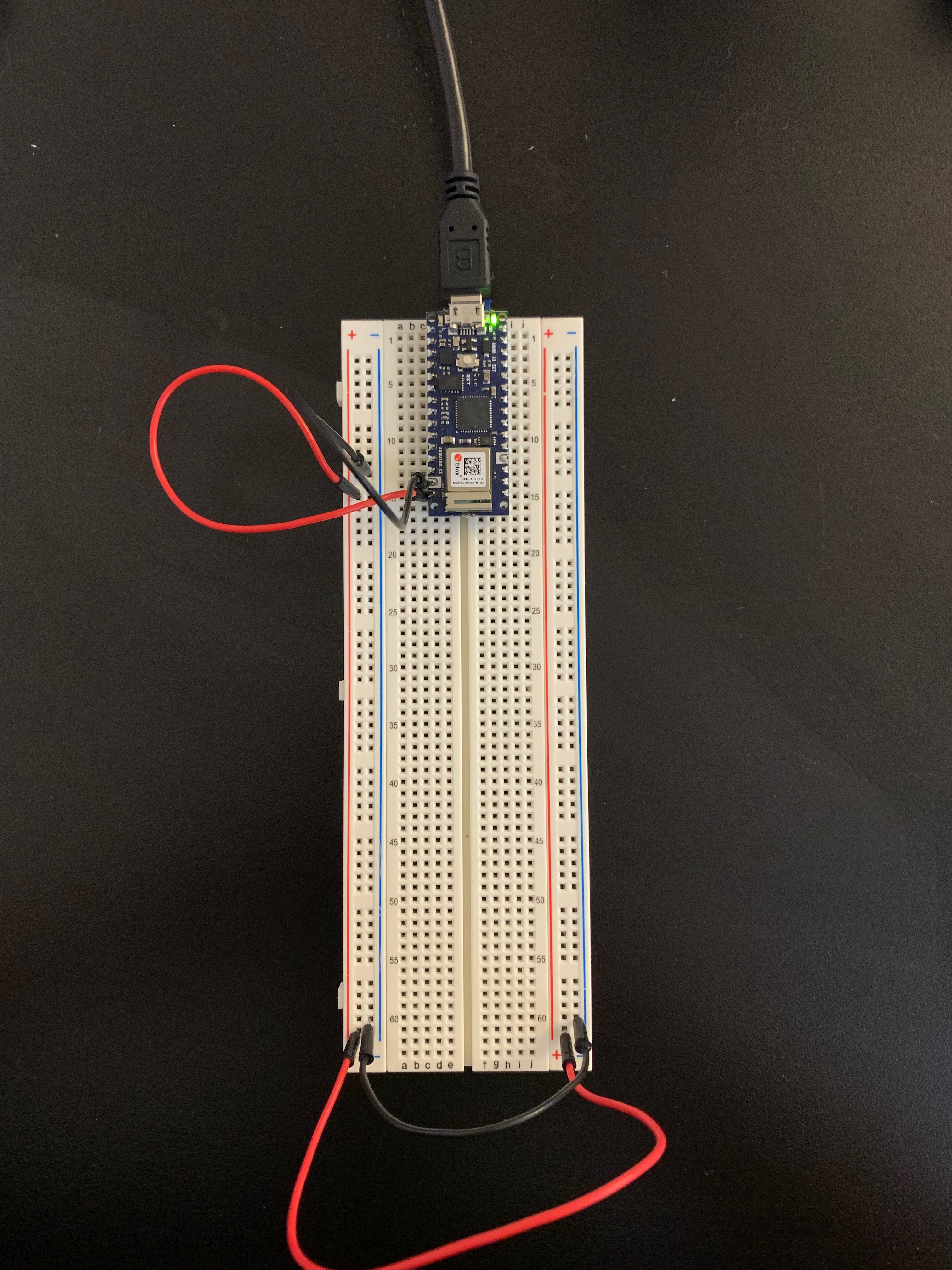
To make LED light nicely, I used 220 ohm resistors. And I write a program that reads digital input on pin 2.
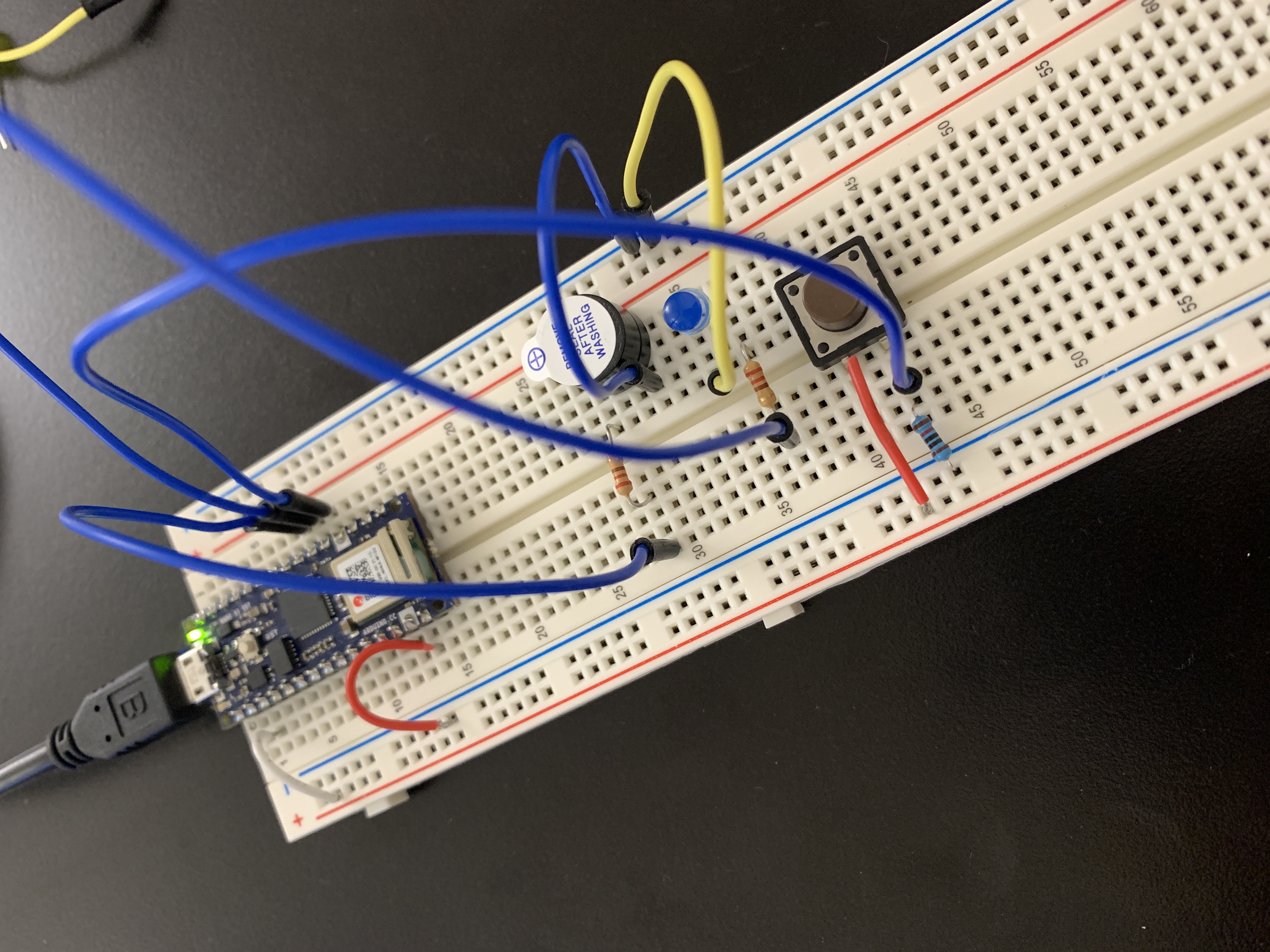 When I replaced one LED with a buzzer, it worked.
︎ Toggle pushbutton
Analog in
1. Add a potentiometer and LED
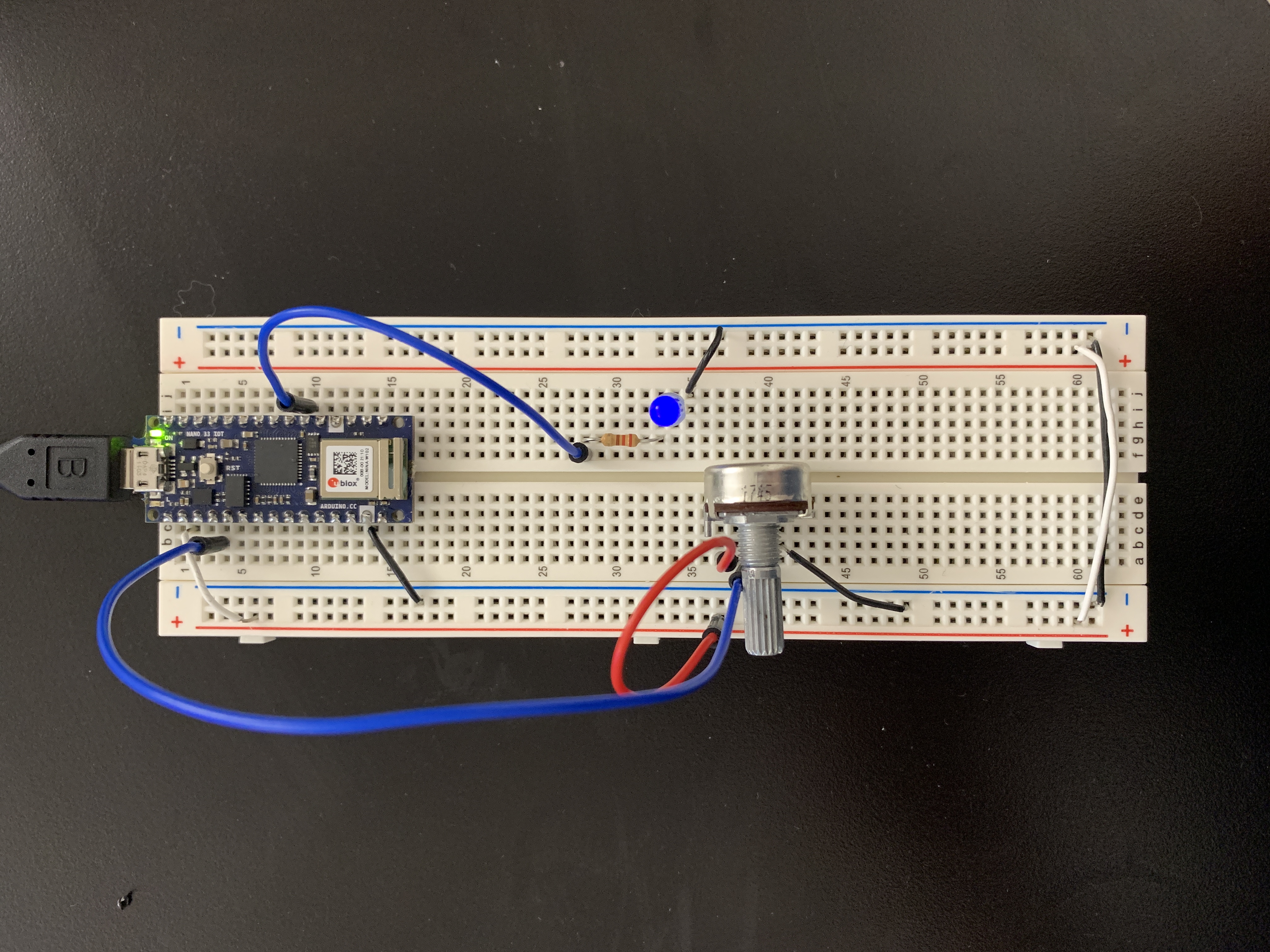
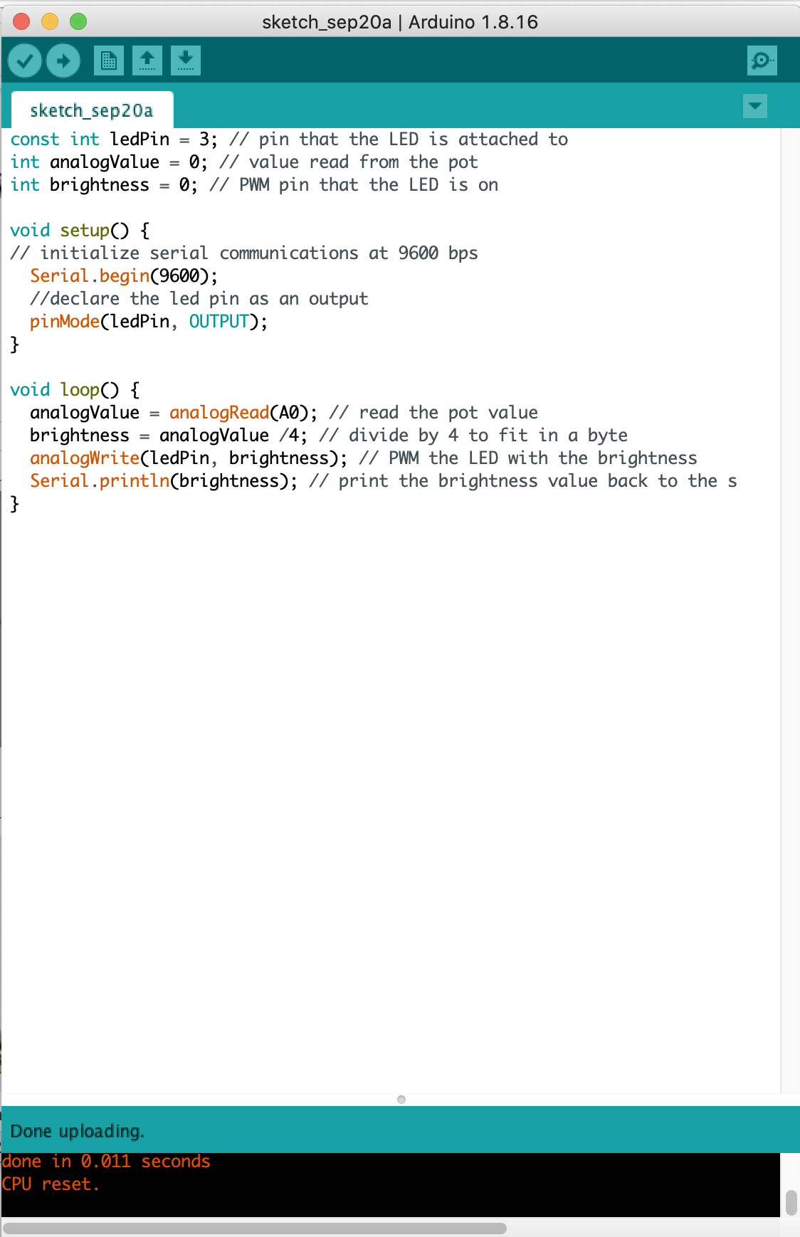
Potentiometer: analog input
LED : output
As turning a potentiometer, LED went brighter. But when turning down, flickering happened. WHY?
It’s fluctuating. Way to remove the noise:
It’s fluctuating. Way to remove the noise:
2.Other variable resistors: FSR(Force Sensitive Resistor), Phototransistor
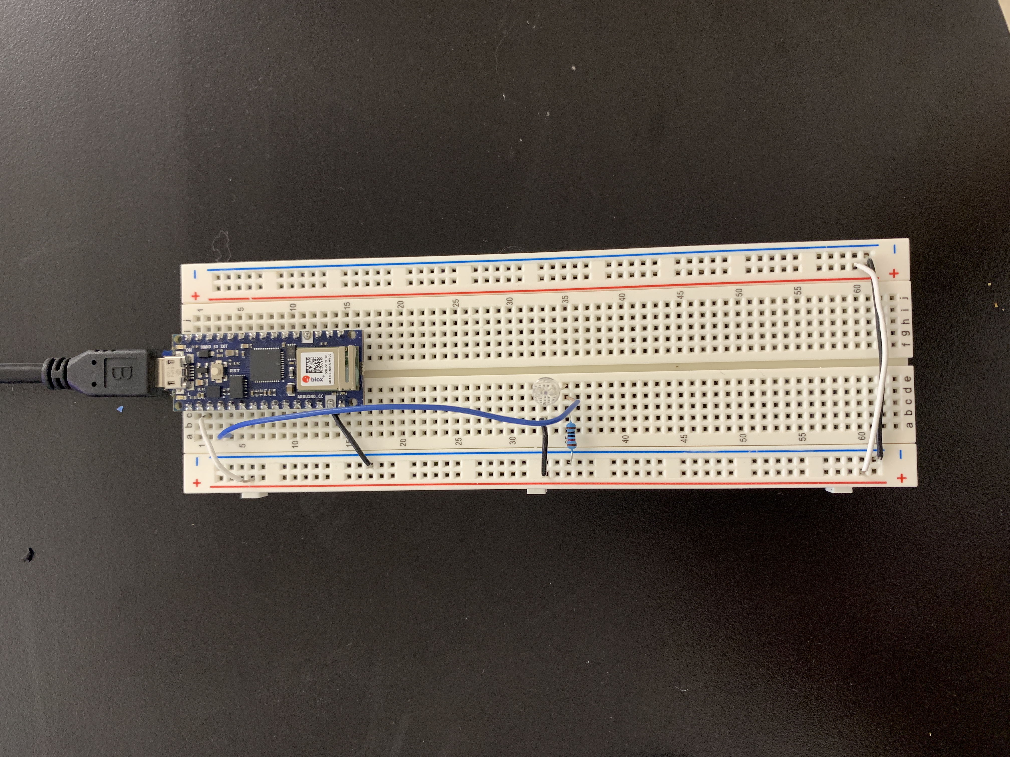 Photosensor:
Analog to digital conversion.
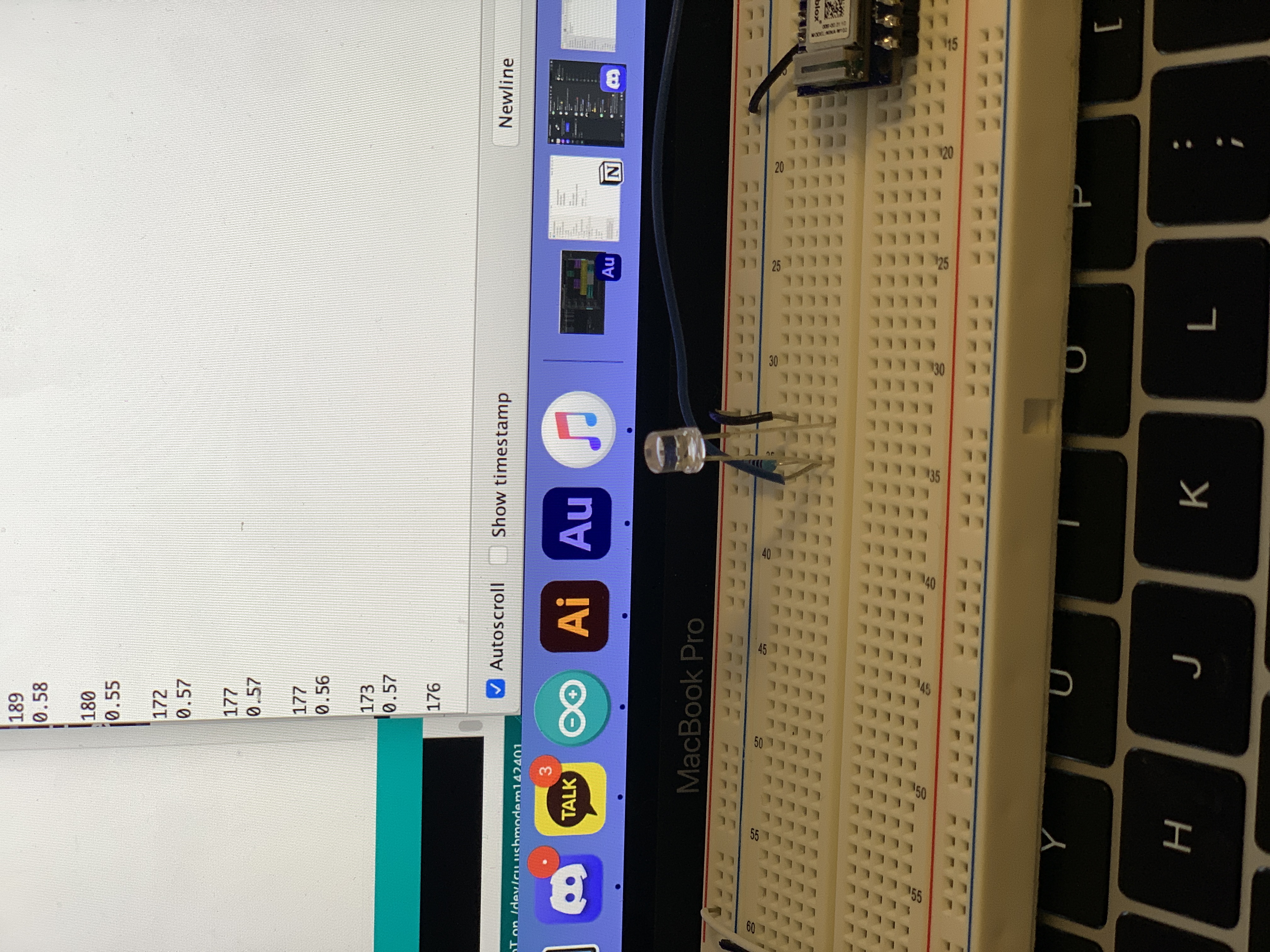
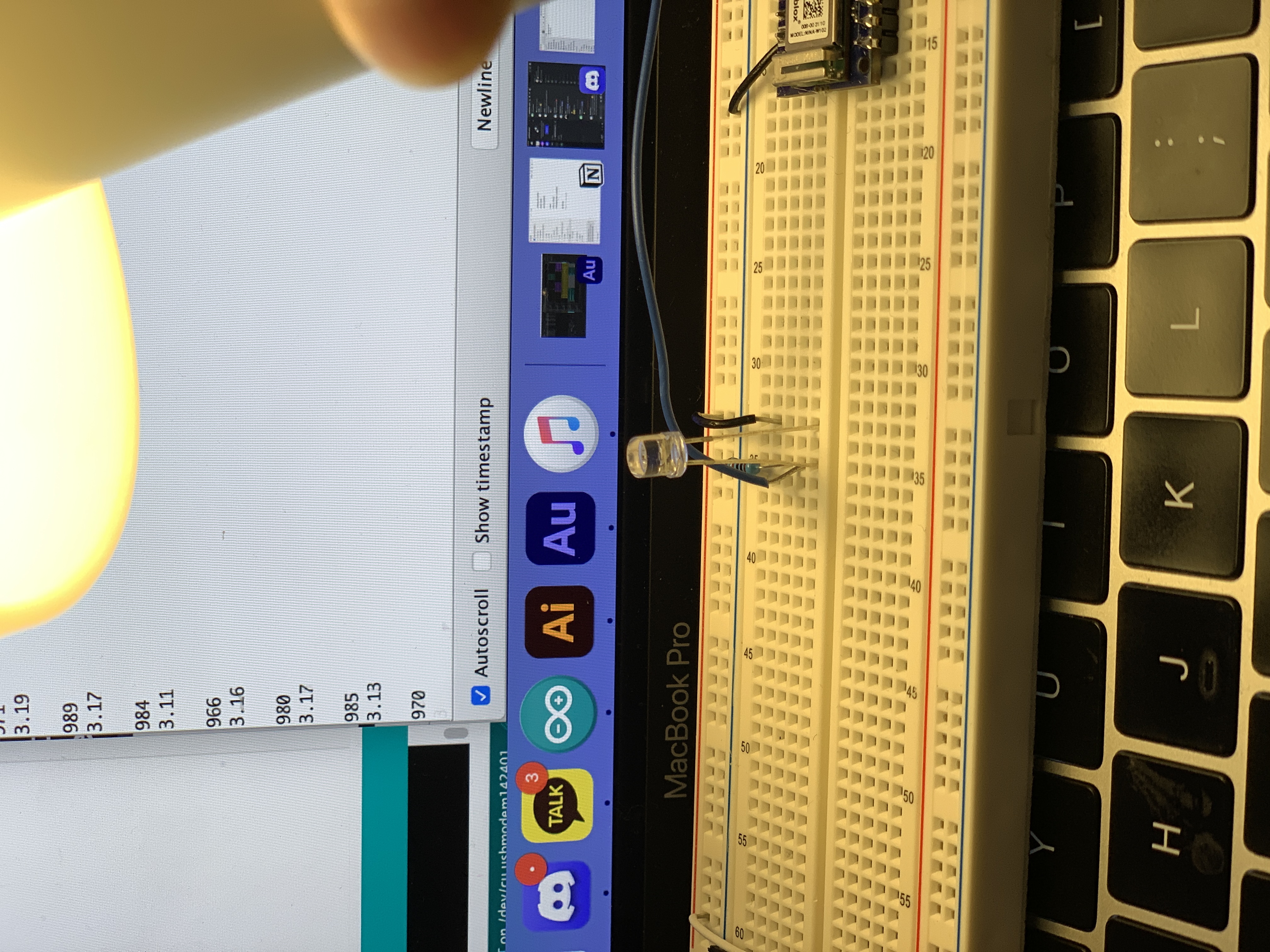
It’s converting that changing voltage into a digital number.
And it can do that at a resolution of ten bits.
It can take 0-5 volts and break it up into for a range from 0 - 1023. (210 =1024)
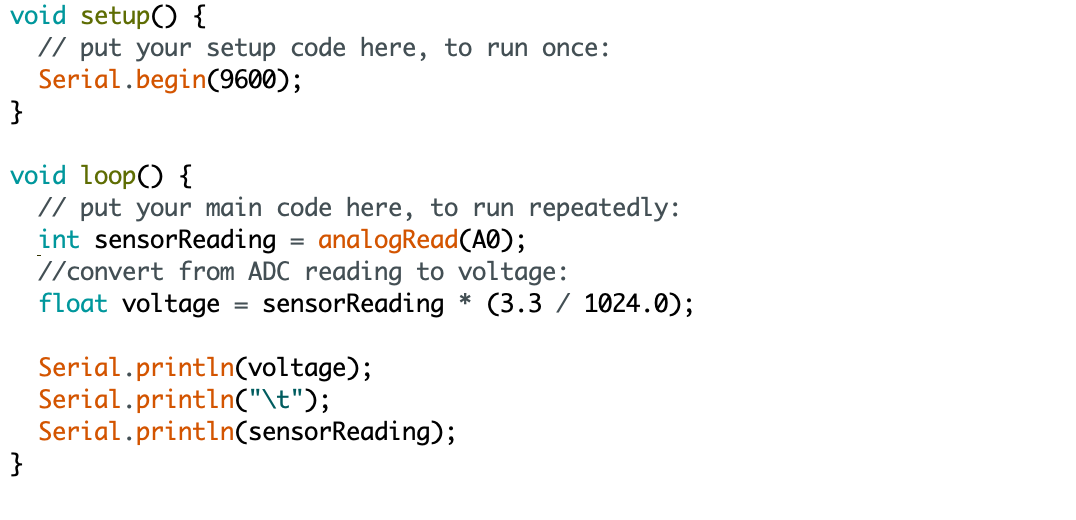
Since I used 3.3V power source from Arduino Nano, I mapped the range that the sensor actually gives as input to the range that the LED needs as output. Here the maximum input range of analog input is from 0 to 3.3 volts. So the voltage on an analog input pin at any point, to extrapolate it in loop() like this.
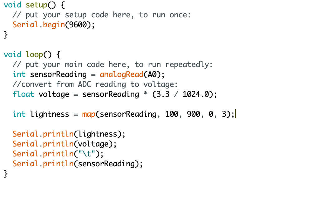 Map voltage ranges into simple 0-3 steps.
It is mapped into the range of 0-3.
Pcom week1
09/14/21Setting up a breadboard
 I have no experince in physical computing, even setting up a breadboard took time. To build different circuits, I supply voltage to both two red side rows of the breadboard.
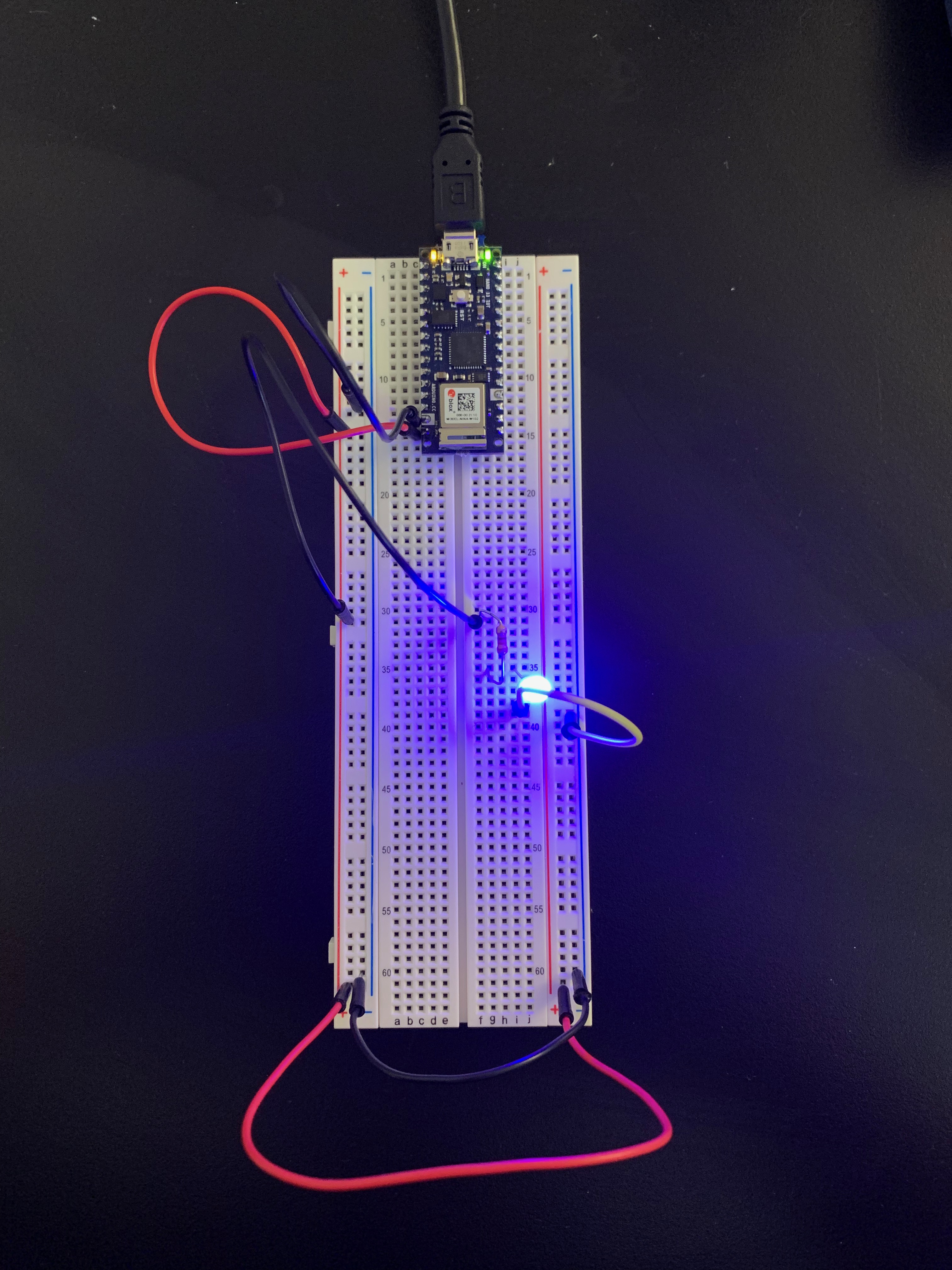

And this is my first lighting LED!
I also tried circuit using battery power and 7805 voltage regulator.
A switched LED circuit
 I used 2 wires, a switch, a LED and 220-ohm resistor.
Components in Series
First, I tried two LED in series. They almost didn’t light up. I guess the aruino nano cannot take the sum of two LEDs and resistor.
When I changed them into a parellel circuit, it works.
Three LEDs in parellel
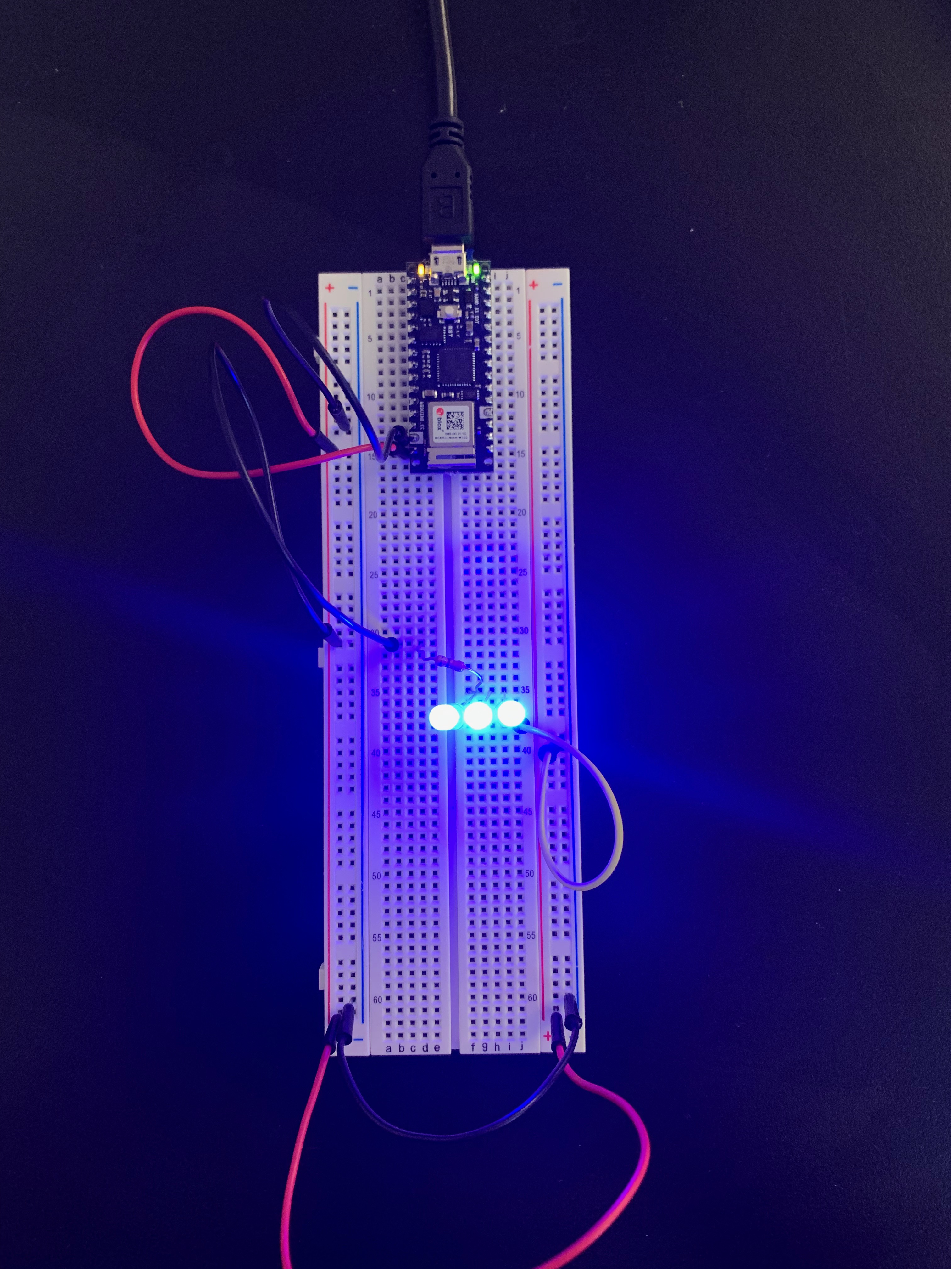 I added one more LED in parellel circuit. It worked fine.
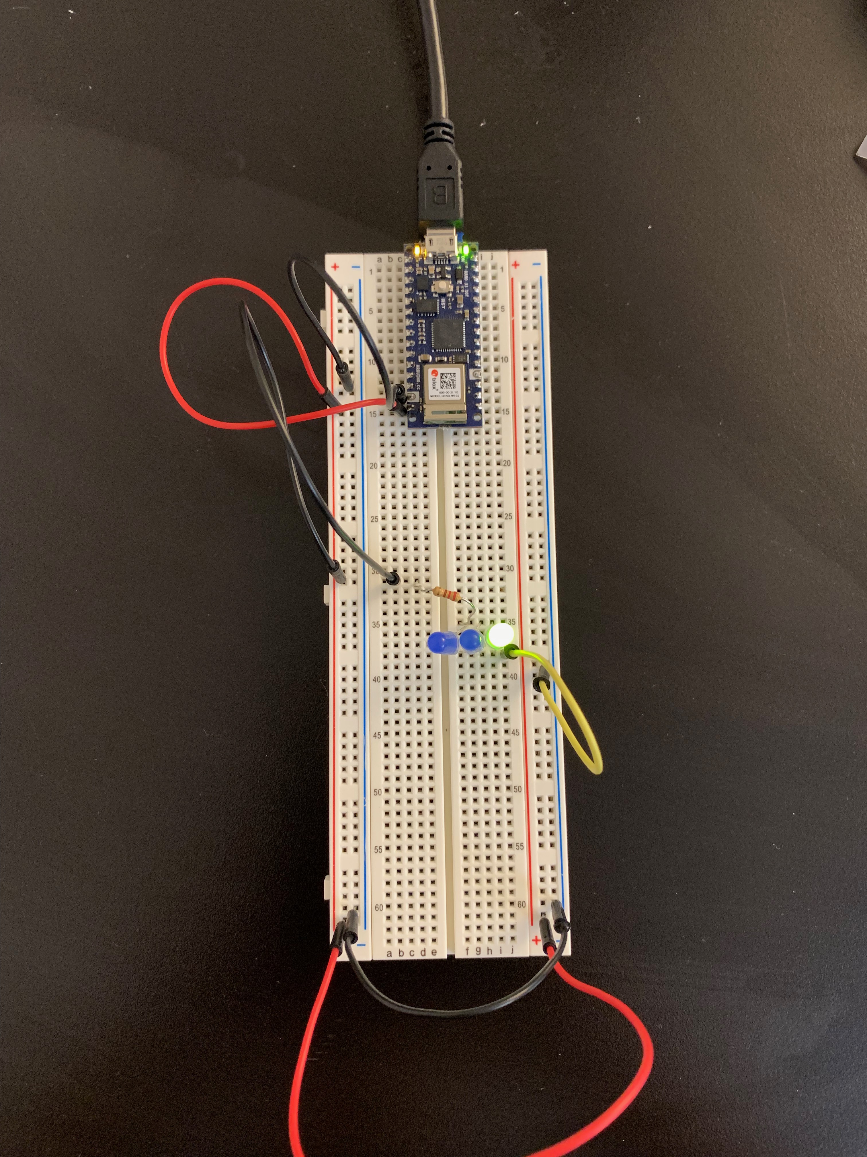 But it didn’t work when replacing one with green. Why?
︎︎︎I measured voltage across LEDs
3 blue LEDS : 2.6 volt each
3 green LEDS : 1.88 volt each
1 green LED : 1.93
Creative switch
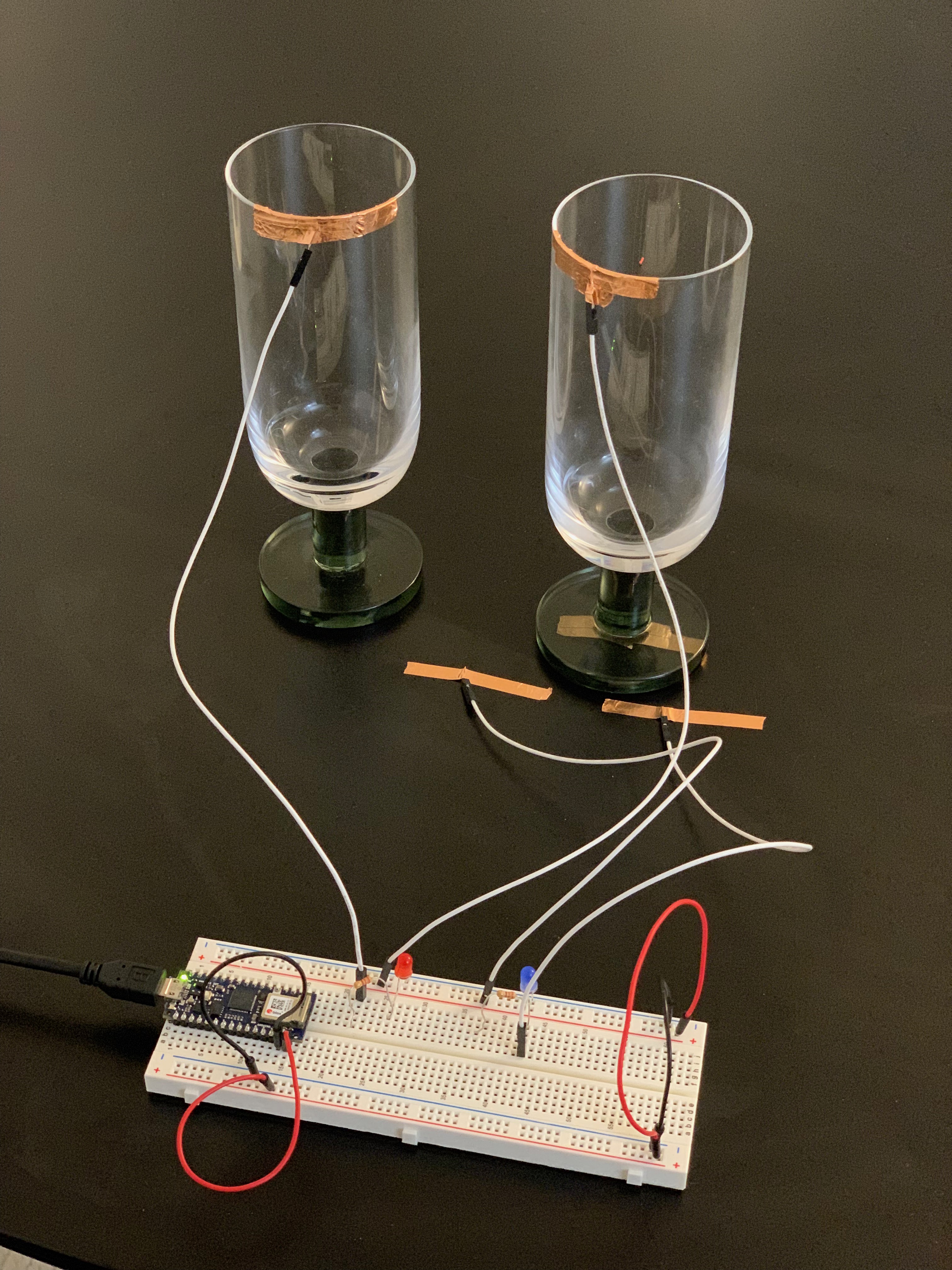 Two interations are needed for lighting each LED. When you clink glasses, the red LED lights up. Then you put down the glass on the table, the blue LED lights up.
Let’s toast to our trial and error!